|
|
|
 |
|
|
|
Description
of Hot Die Casting System
|
|
+
Mold Locking System
- The body is made of FCD material, and
designed with sufficient rigidity and tear and
wear withstanding.
- The locking system is comprised of
integrated four units of axial subsystems,
operating on vertical slide of the walls in
tangent folding operation.
- The locking system is provided with HP
and LP closing device to apply HP closing only
after having secured the close of the metal
molds to avoid damage to the metal
molds.
- The machining plate is gear-driven by an
oil hydraulic motor depending on the size and
the thickness of the metal molds, and an
inching device is provided to facilitate the
adjustment of the entire unit.
- Fixation plate, mold adjustment plate
and slide plate are all given precision
process by taking the parallel and closeness
between arms into consideration.
- Upon replacing the locking mold, retreat
or advance the mold locking mechanism (arm,
sliding plate) to facilitate the replacement.
- The mobile pad for the insertion of the
plunge bar is provided with 12 cavities. Use
the cavities depending on the shape of the
metal molds. The length of the plunge bar must
be correct and arranged the bars in flush; and
have both ends of the bar quenched.
|
|
+
Injection System
- Made of special cast steel with
excellent heat withstanding property; oven
guaranteed with its durability and containing
a preheat field by taking advantage of the
waste heat to preheat the raw metal before
being inputted into the oven. Raw metal not
preheated will cause the danger of splitting
of solution because the water containment
present in the raw metal. The nozzle, overheat
treated gives sufficient durability. A
gooseneck is built in the machine to permit
the direct mounting of the nozzle to the
gooseneck. Grinding is required to eliminate
process traces inside the hole.
- Injection speed has significant impacts
upon the casting property. Therefore, the oil
pipe used on the injection cylinder is
enlarged to induce the direct consumption of
the energy from the pressure accumulator.
- Whereas the injection cylinder is in the
higher temperature status, the water-cooling
system is provided to protect the multiple
pads.
- The reciprocal motion of the injection
oil cylinder will damage the machine in the
absence of loading the piston in the oil
cylinder. If such reciprocal motion without
the piston is required, do it at a slower
speed.
+
Press System
This system operates on the movement of an oil
hydraulic press plate to extrude the finished
product. The length of the extrusion is adjusted
depending on the finished product, and the
extrusion speed is also adjustable.
+
Knock-off Device
Provided over or by the mobile plate, this
device operates on air cylinder to knock off the
finished product at its injection inlet upon
being extruded from the molds.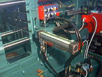
If the molds are designed by following the
principles given below, better knock-off and
reliable casting operation can be achieved:
1. Having the best balance for the molds in the
course of extrusion.
2. Space to admit the finished product knocked
off must be reserved over or by the molds.
3. Minimize protrusions including ventilation on
the molds.
Once the finished product is knocked off, the
nozzle close to the body of the molds will
automatically spray the release agent to
facilitate release the finished product for the
injected alloy.
Fig. 1 shows that the knock-off device is
provided over or by the slide plate.
Fig. 2 shows the operation of the knock off
tooling.
Fig. 3 shows the ejection of the automated oil
spray device.
|
|
+
Automated Lubrication System
Manual refill of grease is not required, and
protect the service life of the console from the
act of omission in manual refill. The automated
lubrication system operates refill at given time
and given amount for maintenance free and
securing the consistency of the mechanism.
Lubrication can be adjusted as applicable.
Control is achieved by the pressure switch where
also tells if there is any damage or oil
leakage.
+
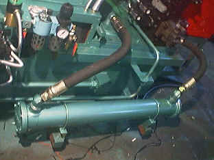
Oil Hydraulic System
The oil hydraulic circuit includes that for
opening and closing molds, injection, extrusion,
console and extraction provided in logic form to
allow operation at high speed, and easier
maintenance.
Speed for mold opening or closing, injection or
other operation is adjustable with good
consistence.
HP seamless steel pipe is used to withstand
vibration, high pressure and oil leakage.
+
Automated Oil
Spray System
Whereas the melting alloy for casting (e.g.
Zinc, Aluminum, or Copper) is inject onto the
surface of the metal molds under high pressure,
high speed and high temperature to create
friction and welding between metals, i.e. the
"sticky mold" . Therefore, before the
injection of the casting alloy, a heat
withstanding and inertia release agent is
sprayed on the surface of the metal molds to
produce a layer of hard film for preventing
direct contact between the alloy and the metal
molds, and improving the appearance and tensile
strength of the finished product. Whereas the
coating of the release agent is very important
process to reduce the nonconformity, please
carefully choose the right type of the release
agent.
Use 1/2 HP, 1/2" PT inlet air compressor to
spray the release agent with the air pressure
maintained within the range of 4~7 kg.
The installation level of the release agent must
not be less than 250 cm, and the pressure shall
be 0~2 kg.
+
Cooling System
- Wider changes exist depending on the ambient temperature and the production. One
3/4" PT is provided to each water inlet of the cooling system for the injection piston, and a
1-1/4" PT is provided on the cooling water inlet at the molds to cool the entire unit. Each is provided with a water volume regulation switch.
- Upon igniting the oven, turn on the cooling water at the oil cylinder piston; and upon closing the operation (to stop the machine), always wait for at least half an hour to turn off the cooling water, or the oil seal to the oil cylinder will be burnt out.
- Cooling water for the mechanical parts is pooled at the same sink to be drained through a
1-1/4" PT.
+
Combustion System
- Diesel or coal oil, is first pressurized by the combustor pump up to 7~9 kg/cm, and then sprayed and atomized out of the nozzle of the combustor to mix with the air delivered from within the gate, and finally ignited by a ignition stick.
- If diesel or coal oil barrel is used for the combustion, the barrel must be provided at a level higher than that of the installation of the combustor, at least 70cm above the ground.
|
|
|
|
|